Installing the Flow 8 in the BSS Case
Note: The installation of the Flow 8 requires technical understanding and some manual dexterity. Please contact our service if you need assistance with installation.
The Flow 8 can be installed in just a few simple steps. In this quick guide, we will show you which steps are necessary to do this. In addition, you will find all steps in our assembly video in a compact and clear manner.

Safety Notice
Before working on the BSS case, unplug it from the socket and also from the case!
Do not touch the installed electronic components when the installation shaft is open. These can continue to carry voltage for a long time even when the mains plug is unplugged and cause an electric shock and/or short circuit.
Please note the further information in our safety instructions.
Necessary tools
- Phillips screwdriver; Type: PH, Size: 0 or 1
- Optional: soft cotton cloth or similar to avoid scratches or damage to the top plate when removing the Flow 8
Preparation
- First, remove all transport locksand protective covers from the recess.
- Use the Phillips screwdriver (PH0 or PH1) to remove the two C-clamps (4x M3x16, 4x M3x25) mounted to the right and left of the recess.
Plug in the cable
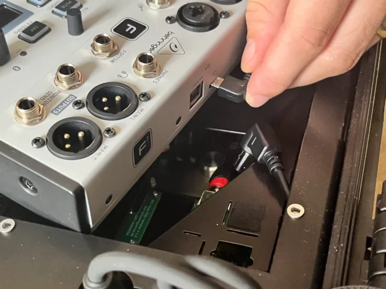
First, plug in the power supply (USB-Micro) and the USB data cable (USB-B) on the Flow 8 (Figure 2). These are labeled accordingly.
Note: Do not pull the cables with force, as this could damage them or pull them out of the sockets built into the case.
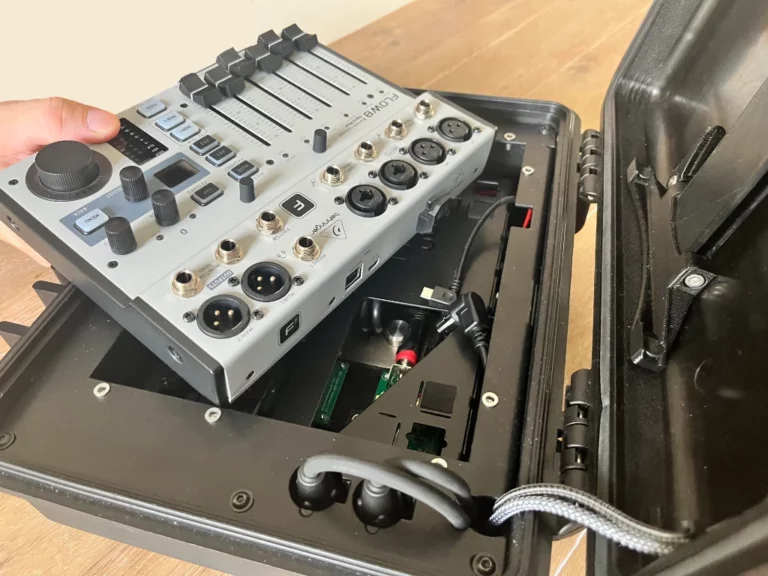
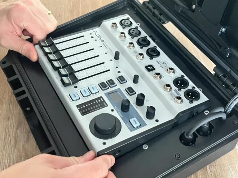
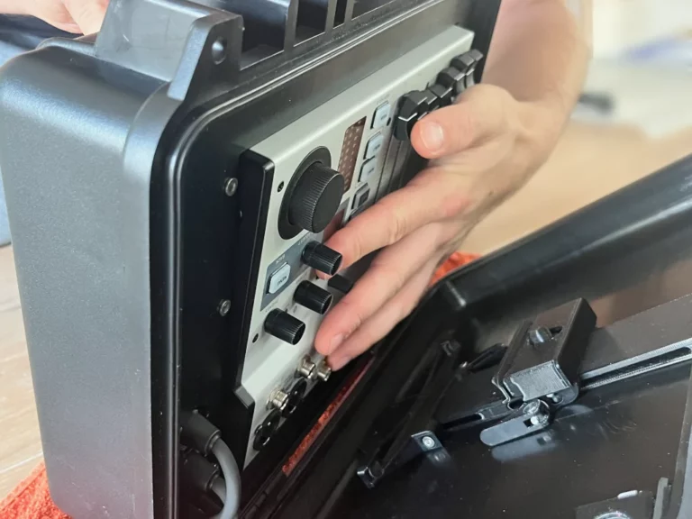
The Flow 8 is inserted by swivelling the back into the recess (Fig. 3).
There are four rectangular recesses on the base plate for the rubber feet of the Flow 8. If necessary, you can move the Flow 8 slightly within the recess after insertion. The Flow 8 fits correctly when its control surface (the volume faders) is at the same height and parallel to the top plate.
Note: Work carefully and under no circumstances press the Flow 8 into the recess with force! If the device is not seated correctly in the recess, carefully remove the Flow 8 (see note “Remove Flow 8”) and check that its rubber feet are in their correct position on the underside (inside the sheet metal beading). If these have shifted, you must bring them back into their positions (their attachment is done with double-sided adhesive tape) Then insert the Flow 8 into the recess again.
The Flow 8 is inserted by swivelling the back into the recess (Fig. 3).
There are four rectangular recesses on the base plate for the rubber feet of the Flow 8. If necessary, you can move the Flow 8 slightly within the recess after insertion. The Flow 8 fits correctly when its control surface (the volume faders) is at the same height and parallel to the top plate.
Note: Work carefully and under no circumstances press the Flow 8 into the recess with force! If the device is not seated correctly in the recess, carefully remove the Flow 8 (see note “Remove Flow 8”) and check that its rubber feet are in their correct position on the underside (inside the sheet metal beading). If they have shifted out of place, you must return them to their original positions (they are secured with double-sided tape). Then reinsert the Flow 8 into the recess.
Swivel in and attach Flow 8
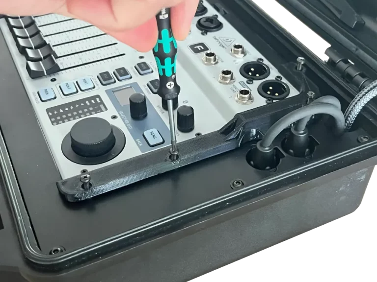
Place the two C-tensioners on the Flow 8. The C-tensioners ensure that the Flow 8 is attached to the recess without play. Screw them into place with a Phillips screwdriver, size PH 0 or 1. The screws M3x25 mm (4x) are used on the raised side, the Screws M3x16 mm (4x) on the flat side of the C-clamps, max. tightening torque 0.2 Nm (! = only lightly apply) (Fig. 4)
First, apply all the screws of the tensioners only lightly until they have found their seat. Then screw them alternately and evenly. If a screw is already stiff when it is placed in the thread, remove it and replace it. In order to grip the beginning of the thread well, it helps to turn the screw a little counterclockwise after attaching it. Please also refer to our video assembly instructions on our support website.
Note: Do not confuse the two screw lengths in their positions. The longer screws can protrude too deep into the case in the wrong position and may cause damage there.
Removing the Flow 8
First, remove a smartphone or tablet that may be inserted in the lid holder. Place the case on a soft surface. Remove the two C-tensioners by loosening all screws with a Phillips screwdriver, size PH 0 or 1. Hold the Flow 8 with one hand and tilt the open case forward on the soft surface until the Flow 8 tilts out of its recess. (Picture 5) Grasp the Flow 8 by the sheet metal housing. Return the case to its working position. Carefully remove the Flow 8 by tilting it upwards and removing it backwards at the same time. Unplug the USB power cable and USB data cable.
Note: Do not pull or hold the controls of the Flow 8 when removing them. These can be removed from their holders or damaged.
Note: when removing the Flow 8, do not pull on the USB cable that is still plugged in. Otherwise, these or the built-in sockets in the device can be damaged.
Inserting your phone or tablet
The holder can accommodate smartphones or tablets up to a maximum size of 260 mm x 178.5 mm x 8.5 mm (WxHxD). The use of larger devices can lead to damage to the holder and the device.
Before inserting the smartphone or tablet, the lower and upper device holders must be adjusted to the correct size.
- Adjust the lower holder. Open the eccentric lever on the lower holder and bring it to the desired height. Close the lever to lock the position.
- Adjust the upper holder. Open the eccentric lever on the top holder and adjust the height to fit your smartphone or tablet. Close the lever to lock the position.
- Insert the device. Swivel your device into the lower holder.
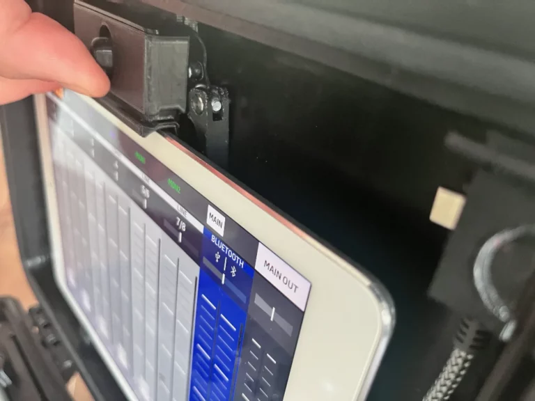
- Adjust the upper holder. Slide the spring-loaded thrust piece up on the top holder and swivel your device into the holder. Allow the print piece to rest gently against the machine (Figure 6).
- Check the fit of the device. The device is ideally inserted when it is held by the pressure piece with maximum tension. Make sure that the inserted device is completely within the holders of the upper and lower brackets. If this is not the case, repeat the adjustment process of the upper holder until the device finds its optimal fit. Your device is now securely fixed in the holder (Fig. 8).
Note: If the device is too loose in the holder, there is a risk that it will detach from the holder during operation or transport and be damaged in the process.
Charging port
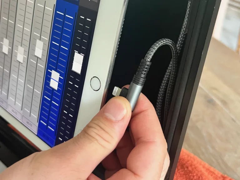
For devices with USB-C and Lightning ports, there are two charging cables in the holder in the upper right corner of the lid. These can be removed from the holder by pulling them downwards and used to charge the devices inserted into the holder.
Note: use only one of the two charging cables at a time to charge an inserted device
Note: remove connectors by pulling on their housing or their strain relief and not by pulling the cables. Otherwise, these can be damaged.
- Plug in the charging cable. The charging port is plugged in from the underside of devices that have enough free space to the edge of the lid. In order not to have to bend the cables too much, the connection cable must be plugged in at a 180° twist for devices that have little space to the side edge (Fig. 6).
- Adjusting the fixation. If the brackets shift when the device is inserted, it is possible to adjust their fixation. To do this, remove the enclosed 4 mm hex wrench from its holder in the right corner of the case lid and place it in the adjustment screw. Open the eccentric lever and hold it against twisting. Tighten the screw by a maximum of 30° (clockwise) at a time. Close the eccentric lever and test the holding force again. If necessary, the adjustment in several small steps is necessary.
Note: if too much force is needed to close the eccentric lever, cancel the process and loosen the screw a little. Test again. The lever must not be closed with high force. Otherwise, there is a risk of material breakage.
The ideal preload of the screw with the eccentric lever closed is 0.14 Nm (only very lightly applied)
Closing the lid or/and transporting the case with the device inserted
Before closing the lid, check that all connectors and cables have been removed from the Flow 8 and that the optional main-out XLR connectors are also in their parking position (see “Unplugging and Inserting the Connectors into Their Parking Position” in our Owner’s Manual on page 17).
Although there is enough space between the inserted device and the Flow 8 with a suitable device, there is a possibility that damage to the device can occur when closing the lid or during transport. Therefore, remove the device inserted into the holder before closing the lid or transporting the case.